Bryant Furnace often generate error codes indicating various common malfunction situations. These codes signify potential issues that may impact the device’s performance. When users encounter these error codes, understanding this information is crucial for finding a quick and effective solution. The article focuses on Bryant Furnace error codes, explaining the possible meaning of each code. This enables users to better diagnose problems and enhance the efficiency of their boilers.
Most Common Codes
If status code recall is needed disconnect the “R” thermostat lead, reset power, and put setup switch “SW1-1” in the ON position. To clear the status code history put setup switch “SW1-1” in the ON position and jumper thermostat terminals “R”, “W/W1”, and “Y/Y2” simultaneously until status code #11 is flashed.
| Error Codes | Meaning |
|---|---|
| 11 | No Previous Code – Stored status codes are erased automatically after 72 hours or as specified above. |
| 12 | Blower On After Power Up – (115 VAC or 24 VAC) – Normal operation. Blower runs for 90 seconds, if unit is powered up during a call for heat (R-W/W1 closed) or (R-W/W1 opens) during the blower on-delay period. |
| 13 | Limit Circuit Lockout – Lockout occurs if the limit, or flame rollout switch is open longer than 3 minutes or 10 successive limit trips occurred during maximum-heat. Control will auto reset after 3 hours. |
| 14 | Ignition Lockout – Control will auto reset after 3 hours. |
| 15 | Blower Motor Lockout – Indicates the blower failed to reach 250 RPM or the blower failed to communicate within 30 seconds after being turned ON in two successive heating cycles. Control will auto reset after 3 hours. |
| 21 | Gas Heating Lockout – Control will NOT auto reset. Check for: - Stuck closed gas valve relay on control. - Miswire or short to gas valve BLUE wire. |
| 22 | Abnormal Flame-proving Signal – Flame is proved while gas valve is de-energized. Inducer will run until fault is cleared. Check for: - Leaky gas valve. - Stuck-open gas valve. |
| 23 | Pressure Switch Did Not Open – Check for: - Obstructed pressure tubing. - Pressure switch stuck closed. |
| 24 | Secondary Voltage Fuse is Open – Check for: - Short circuit in secondary voltage (24 VAC) wiring including thermostat leads. Disconnect thermostat leads to isolate short circuit. |
| 25 | Model Selection or Setup Error – If status code 25 only flashes 4 times on power-up the control is missing its model plug PL4 and is defaulting to the model selection stored in memory. |
| 31 | Medium Pressure Switch, High Pressure Switch, or Psr Relay Did Not Close Or Reopened – Indicates the medium or high pressure switch input failed to close on a call for intermediate- or maximum-heat, or opened during a heat cycle. PSR relay may be defective. |
| 32 | Low Pressure Switch Did Not Close or Reopened – Indicates the low pressure switch input failed to close on a call for heat, or opened during minimum-heat. If opens during blower on-delay period, blower will come on for the selected blower off-delay. If opens within 5 minutes after ignition the next heating cycle will be restricted to maximum-heat. |
| 33 | Limit Circuit Fault – Indicates the limit, or flame rollout is open or the furnace is operating in maximum-heat only mode due to 2 successive limit trips while operating at any rate less than or equal to 71% of maximum rate. Blower will run at intermediate heat airflow for 4 minutes or until open switch remakes whichever is longer. |
| 34 | Ignition Proving Failure – Control will try three more times before lockout #14 occurs. If flame signal is lost during blower on-delay period, blower will come on for the selected blower off-delay. |
| 35 | Gas Valve Fault – Indicates the modulating gas valve failed to respond to a command from the furnace control or power to the gas valve electronics was interrupted. Check for: - Intermittent RED, YELLOW, or ORANGE wire at gas valve or PL8 connections |
| 41 | Blower Motor Fault – Indicates the blower failed to reach 250 RPM or the blower failed to communicate within the prescribed time limits. Thirty seconds after being turned ON or ten seconds during steady-state operation. |
| 42 | Inducer Motor Fault – Indicates the inducer has not started within 20 seconds after a call for heat, the inducer motor RPM is outside its valid range of operation, or the inducer RPM signal was lost for 5 seconds during operation. |
| 43 | Low Or Medium Pressure Switch Open While Medium or High Pressure Switch is Closed – Check for: - Low inlet gas pressure (if LGPS used). - Plugged condensate drain. - Improper pressure switch wiring. - Water in vent piping, possible sagging pipe. - Low or Medium pressure switch stuck open. - Disconnected or obstructed pressure tubing. |
| 45 | Control Circuitry Lockout – Auto-reset after 1 hour lockout due to: - Flame sense circuit failure. - Gas valve relay stuck open. - Software check error. - Reset power to clear lockout. Replace control if status code repeats. |
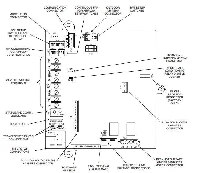
Modulating Furnace Control
Heat Pump Defrost
When installed with a heat pump, the furnace control automatically changes the timing sequence to avoid long blower off times during demand defrost cycles. Whenever W/W1 is energized along with Y1 or Y/Y2, the furnace control CPU will transition to or bring on the blower motor BLWM at cooling airflow, minimum-heat airflow, or the midrange airflow, whichever is lowest. The blower motor BLWM will remain on until the main burners ignite then shut OFF and remain OFF for 25 seconds before coming back on at modulating heat airflow.
When the W/W1 input signal disappears, the furnace control begins a normal inducer post-purge period while changing the blower airflow. If Y/Y2 input is still energized the furnace control CPU will transition the blower motor BLWM airflow to cooling airflow. If Y/Y2 input signal disappears and the Y1 input is still energized the furnace control CPU will transition the blower motor BLWM to low-cooling airflow.
If both the Y1 and Y/Y2 signals disappear at the same time, the blower motor BLWM will remain on at minimum-heat airflow for the selected blower-OFF delay period. At the end of the blower-OFF delay, the blower motor BLWM will shut OFF unless G is still energized, in which case the blower motor BLWM will operate at continuous blower airflow.
- Rapid Flashing Amber Led – Indicates line voltage polarity is reversed, furnace is not grounded, or the transformers are out of phase in twinned units.
- Improper Cooling Air Flow – Generally, this indicates the Y/Y2 thermostat lead is not properly connected. If User Interface is connected to ABCD connector then the wrong size outdoor unit could be configured in the User Interface.
- Minimum And/or Maximum Heat Temperature Rise Too Low – Generally, this indicates the furnace is extremely underfired.
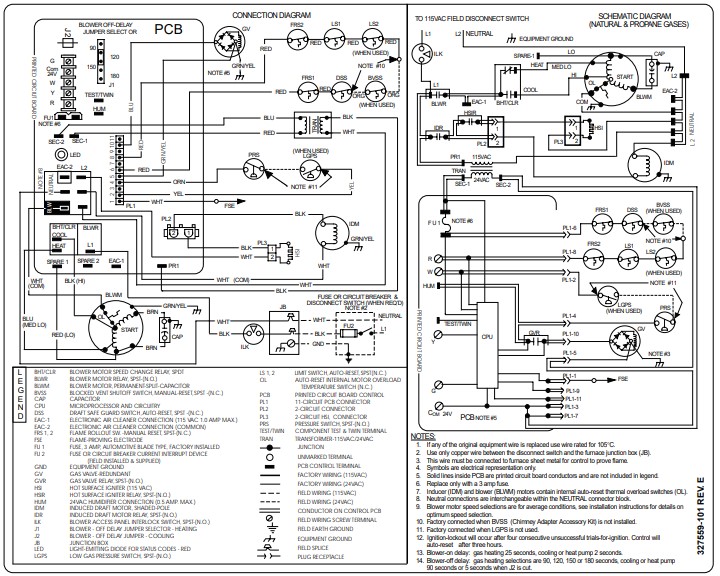
Wiring Diagram
Manual Pdf
Bryant 310AAV AHAA AHAJ Installation Instructions Manual PDF
Bryant 355MAV Installation, Start-Up, And Operating Instructions Manual PDF