Carrier furnace error codes are crucial for swiftly identifying issues in heating systems. These codes serve as a guide for users to monitor and maintain their devices efficiently. Each code pinpoints a potential malfunction, providing quick solutions. Understanding and addressing error codes accurately is essential to enhance the reliability of the heating system.
Most Common Codes
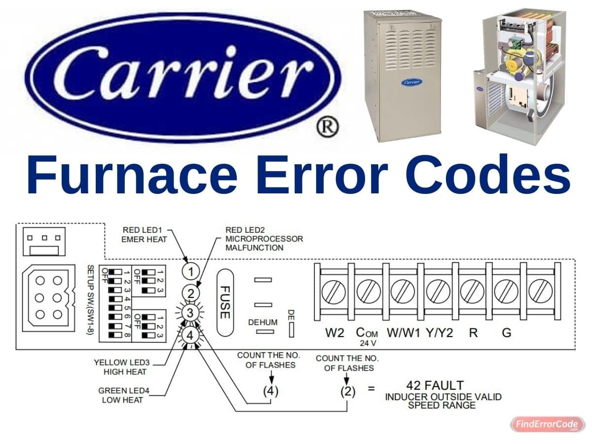
If your furnace is not operating or not performing properly, you may save the expense of a service call by checking a few things yourself before calling for service. The status codes are a 2 digit number. The first digit is determined by the number of flashes of the yellow light and the second digit is determined by number of flashes of the green light.
| Error Messages | Meaning |
|---|---|
| 11 | No fault in recent history display. Indicates no faults have occurred within last five cycles. To read recent fault history put setup switch "SW-1" in the "ON" position. To clear recent fault history, put setup switch "SW-1" in the "ON" position and jumper thermostat terminals "R", "W/W1", and "Y/Y2" simultaneously until an "11" is flashed. |
| 12 | Blower calibration lockout. Indicates RPM calculated for low heat was less than 250 RPM or greater than 1300 RPM on two successive attempts. Auto reset after three hours. |
| 13 | Limit switch lockout. Indicates the occurrence of 10 successive limit trips during high heat or three successive limit trips during low heat. Auto reset after three hours. Check for: - Improper or misaligned limit and/or limit shield. - Improper high or low heat gas input adjustment. - Stuck high heat solenoid in gas valve. |
| 14 | Ignition lockout. Control will auto-reset after three hours. |
| 21 | Invalid model selection. Indicates model plug is missing or incorrect. See wiring diagram for correct connector jumper location. |
| 22 | Setup error. Indicates setup switch "SW-1" or SW-6" is positioned improperly. The following combinations will cause the fault. - Thermostat call with "SW-1" "ON". - Thermostat call with "SW-6" "ON". -"SW-1" and "SW-6" both "ON" together. |
| 23 | Invalid blower airflow selection. Indicates improper "A/C" or "CF" switch setting. The 042 and 14 units can deliver 1-1/2 to 3-1/2 tons A/C and 600 to 1400 CFM for continuous fan. The 060 and 20 unit can deliver 2 to 5 tons A/C and 800 to 2000 CFM for continuous fan. If code is flashing unit will default to closest allowable airflow. |
| 24 | Secondary voltage fuse is open. Check for: Short circuit in secondary voltage (24V) wiring. |
| 31 | High pressure switch fault. Indicates high pressure switch is closed at call, or in low heat, or fails to close after call, or opens in high heat. Check for: - Plugged condensate drain. - Water in vent piping, possibly sagging pipe. - Improper pressure switch wiring or pressure switch tubing connections. - Failed or "Out-of-Calibration" pressure switches. |
| 32 | Low pressure switch fault. Indicates low pressure switch is closed at call, or fails to close after call, or opens during operation. Check for: - Plugged condensate drain. - Water in vent piping, possibly sagging pipe. - Improper pressure switch wiring or pressure switch tubing connections. - Failed or "Out-of-Calibration" pressure switches. |
| 33 | Limit or flame roll-out switch is open. Indicates the limit, rollout switch or auxiliary limit switch is open or the unit is operating in high heat only mode due to two successive low heat limit trips. Check for: - Improper or misaligned limit and/or limit shield. - Improper low heat gas input adjustment. - Stuck high heat solenoid in gas valve. |
| 34 | Ignition proving fault. Control will try three more times before a lockout #14 occurs. Check for: - Gas valve defective or gas valve turned "OFF". - Defective Hot Surface Ignitor - Manual valve shut-off. - Low inlet gas pressure. |
| 41 | Blower outside valid speed range. Indicates the blower is not operating at the calculated RPM. If this fault occurs in conjunction with fault #44 check wiring to motor otherwise refer to the trouble-shooting guide. |
| 42 | Inducer outside valid speed range. Indicates the inducer is not operating at the calculated RPM, or has not started within 10 seconds after a call for heat. Check wiring to motor otherwise refer to the trouble-shooting guide. |
| 43 | Pressure switch calibration fault. Indicates the low and high pressure switch "make" points during high heat purge are not within the calibration range. Check for: - Plugged condensate drain. - Water in vent piping, possibly sagging pipe. - Improper pressure switch wiring or pressure switch tubing connections. - Failed or "Out of Calibration" pressure switches. |
| 44 | Blower calibration fault. Indicates the calculated blower speed is below 250 or above 1300 RPM. Unit will default to low or high heat mode if possible. If this fault occurs in conjunction with fault #41 check wiring to motor otherwise refer to the trouble-shooting guide. If this fault occurs by itself check for undersized ductwork, or excessive static caused by a dirty filter, or closed registers. |
| 13 or 33 | Limit Switch Lockout |
| 14 or 34 | Ignition Lockout or Ignition Proving Fault |
| Red Led1 On | Furnace is operating in emergency heat. |
| Red Led2 On | The microprocessor has malfunctioned. To reset: Put setup switch "SW-1" in the "ON" position and jumper thermostat terminals "R", "W/W1", and "Y/Y2" simultaneously with the door switch pushed in and power to the unit "ON". Disconnect jumper and place setup switch in the "OFF" position. If LED2 reappears replace main control board. |
| Yellow Led3 On | Furnace is operating in high heat. |
| Green Led4 On | Furnace is operating in low heat. |
| Red Led2 Flashing | Line voltage polarity is reversed. |
Furnace Components Meaning

Filtering Out Trouble
A dirty filter will cause a loss of airflow in your duct system. When excessive loss of airflow occurs, the furnace may cycle on the safety controls. If this condition is left unattended, the furnace will eventually lockout. It is recommended that the furnace filter be checked every 3 or 4 weeks and cleaned if necessary.
The air filter is normally located in the blower compartment. If filter has been installed in another location, contact your dealer for instructions. To inspect, clean and/or replace the air filter(s), follow these steps:

- Turn off electrical supply to the furnace.
- Remove furnace access door.
- Remove blower access panel.
A Checkup Checklist
Your furnace represents an important investment in your family’s comfort and your home’s value. To keep it performing properly and as a preventative to future problems, have a trained service specialist give your furnace a professional check-up annually. The following checklist can be used as a guideline to proper service:
- Inspect all flue gas passages, burners, heat exchangers, coupling box(es), and inducer assembly.
- Inspect all combustion-air and vent piping inside structure and pipe terminations outside the structure.
- Check gas pipes leading to and inside of your furnace for leaks.
- Inspect and clean the blower motor and wheel.
- Inspect and change or clean air filter(s) if necessary.
- Inspect all supply- and return-air ducts for obstructions, air leaks, and insulation. Remedy any problem when necessary.
If Furnace Fails To Operate
Follow this checklist step by step, advancing to the next step only if furnace fails to start.
- Check thermostat for proper temperature. Is thermostat set above room temperature?
- Is thermostat switch on HEAT?
- Check fuses and circuit breakers. Is electrical supply on?
- Is manual shut-off valve in gas supply pipe in open position? (Follow start-up procedures if you open gas valve.)
- Is control knob on gas valve in ON position? (Follow startup procedures if you must reset knob to ON.)
- Check for obstructions around the vent termination.
If the furnace still fails to operate, call your service representative.
This furnace has an LED operation and fault code display to aid the installer, service technician, or homeowner while installing or servicing the unit. The LED code can be seen by removing the access door and viewing the LED(s) through the view port in the blower access panel.
Connection and Schematic Diagram


Manual
User’s information manual for the operation and maintenance of your new gas-fired furnace PDF