
Panasonic is one of the top TV manufacturers in the world, offering not just home entertainment systems but inflight entertainment systems as well. Founded 104 years ago, this Japanese multinational corporation was once a light bulb socket manufacturer. Spending its wings Panasonic took a leap of faith and is not one of the leading names in the market.
Apart from catering to a wide range of industries, They offer a wide range of selections when it comes to televisions, ensuring you get one based on your unique requirements. Offering you top-of-the-line choices that fit in your home or workspace in a way that enhances your overall experience.
Panasonic might be one of the oldest manufacturers in the world, but its TVs are as open to errors as any other company. To help you out we have listed down some of the most common error codes for Panasonic TVs. Start by noting down the error code, and match it using the list below. Once you have the error code you can easily work your way to the fix.
Codes List
2010 Panasonic 3D Plasma TV (13th Generation). Power LED Error Code Definition.
The following table identifies the areas where a problem is suspected according to the number of times that the POWER LED blinks.
| Power Led Error Codes | Circuit Monitored - Conditions Triggering The Shutdown |
|---|---|
| 1 Blinlk | Panel Information SOS. Panel Alarm SOS. Communication problem between the System CPU (IC1100) and the Panel CPU (IC9003). |
| 2 Blinlk | P15V form the P board. Missing P15V: P15V is not been generated by the P board. P15V is been affected by one of the boards it is connected to (A short circuit of the P15V). Wrong diagnostic by the D board. |
| 3 Blinlk | P3.3V from the D board. Missing P3.3V Reasons: The A board is not generating the 3.3V. The 3.3V is been affected by one of the C boards or the Panel (A short circuit of the P3.3V). Wrong diagnostic by the D board. |
| 4 Blinlk | Power Supply output voltages. Regulation issues with any of the voltages output from the power supply. Wrong diagnostic by the D board. |
| 5 Blinlk | P5V from the A board. Missing P5V Reasons: The A board is not generating the 5V. The 5V is been affected by the SC, SS, A, or C2 board (A short circuit of the P5V). Wrong diagnostic by the D board. |
| 6 Blinlk | SC Energy Recovery Circuit. An increase or reduction of the Energy Recovery Circuit output (MID). Open connection between connector D20 on the D board and SC20 on the SC board. Open connection between any of the ribbon cables on the C boards and the D board. Open connection between the ribbon cable/cables interconnecting the C boards. Wrong diagnostic by the D board. |
| 7 Blinlk | Scan Drive Circuit and Connection between the SC board and the SM board. Missing Vsus. Abnormality of the scan circuit output, the 15V_F, the scn_pro, and Vscn circuit. Loose or open Connection between the SC board and the SM board (SC41, SC42, SC46). Open or loose connection between connectors SC2/P2. Wrong diagnostic by the D board. Defective panel. |
| 8 Blinlk | Sustain Drive Circuit and Connection between the SS board and the Panel. Abnormality of the sustain drive circuit. Open or loose connection between the SS bd and FPCs from the panel. Open or loose connection between connectors C10/C20. Wrong diagnostic by the D board. Defective panel. |
| 9 Blinlk | Discharge Control Circuit (IC9300). Failure of IC9300 Wrong diagnostic by the D board. |
| 10 Blinlk | Abnormalities of the F+15V. Reasons: The P board is not generating the F+15V. SUB Voltages are affected by the K board or by metal object present in the SD card slot. Shorted Vsus (By the SS board or SC board). Shorted Vda (By the panel, or any of the C board). Wrong diagnostic by the A board. |
| 11 Blinlk | Fan SOS. Fans. A board. Connection and Cables between fans and A board. |
| 12 Blinlk | Sound SOS. Pinched speaker wires. A board. Speakers. |

SOS Detect (Shutdown)
When an abnormality occurs in the unit, the “SOS Detect” circuit is triggered and the TV shuts down. The power LED on the front panel will flash a pattern indicating the circuit that has failed.
Cautions: If the power LED continues to blink even after the TV is unplugged, press and hold the power switch on the TV for a few seconds until the LED turns off. Some steps require removal of connectors and sometimes PC boards removal. Do not allow the TV to run for more than 30 seconds while connectors or boards are disconnected.
SOS Detect Circuit
Protection circuits are incorporated in the unit to prevent the failure of a single circuit or component from creating catastrophic damage. A shutdown condition occurs when a there is an over voltage, a short or a drop in any of the voltage lines. Also when the fans are drawing more current than normal the shutdown circuit is triggered. Normally the CPU of the D board and the CPU of the A board detect when a shutdown condition has been triggered. When an abnormality has occurred, the unit protection circuit operates and the TV is reset to the stand-by mode. At this time, the defective block can be identified by the number of blinks of the POWER LED on the front of the unit.
IC9003 of the D board detects conditions that make the power LED blinks 2, 3, 4, 5, 6, 7, 8, or 9 times. IC 1100 on the A board detects conditions that make the power LED blinks 10, 11, and 12 times.
1 Blink SOS: Communication error between System CPU (IC1100) and Panel CPU (IC9003).
2 Blinks SOS: Pin 62 of the CPU IC9003 monitors the 15V line. During normal operation, the pin 62 is high. If the 15V line is missing or shorted, a low is provided to pin 62. As a result, the unit shuts down and the power LED blinks 2 times.
3 Blinks SOS: IC9802 is a 3.3V regulator located on the D board. Its output is monitored by IC9003. If the 3.3V is not present at pin 61, the MPU shuts down the unit. The power LED blinks 3 times.
4 Blinks SOS: When an over voltage condition of the voltage lines from the power supply occurs, pin 16 of IC701 goes high. This high is provided to pin 67 of IC9003 of the D board triggering the “POWER SOS” circuit. When this happens, the TV shuts down and the power LED blinks 4 times.
5 Blinks SOS: Pin 60 of the CPU IC9003 monitors the 5V line. During normal operation, the pin 69 is high. If the 5V line is missing or shorted, a low is provided to pin 60. As a result, the unit shuts down and the power LED blinks 5 times.
6 Blinks SOS: Pin 65 of the CPU IC9003 monitors the status of the SC board. During normal operation, a low is applied to pin 65. If the SC board becomes defective, a high is provided to pin 65. As a result, the unit shuts down and the power LED blinks 6 times.
7 Blinks SOS: Pin 68 of the CPU IC9003 monitors the status of the SC, SU, SD board. During normal operation, a low is applied to pin 68. If the SC, SU, or SD board becomes defective, a high is provided to pin 68. As a result, the unit shuts down and the power LED blinks 7 times.
8 Blinks SOS: Pin 66 of the MPU IC9003 monitors the status of the SS board. During normal operation, pin 7 of connector SS33 outputs a low to pin 66. If the SS board becomes defective, a high is provided to pin 66. As a result, the unit shuts down and the power LED blinks 8 times. Another SOS Detect circuit in the Sustain board monitors for physical connection between the SS board and the panel. If any of the flex-cables from the panel is not connected or is not properly seated, a high is provided to pin 66 of the CPU in the D board. When this happened, the TV shuts down and the power LED blinks 8 times.
9 Blinks SOS: Pins 85 and 86 of the MPU IC9003 monitor the status of IC9300 and IC9400. During normal operation, pin 85 and pin 86 are low. A malfunction of IC9300 or IC9400 triggers a shutdown and the power LED blinks 9 times.
11 Blinks Error Code Explanation: The internal temperature of the unit is monitored by the digital temperature sensor (IC9002). Variations in temperature are sensed by the IC and reported to the D board MPU (IC9003) via the SDA02 bus line. IC9003 then conveys the information to the A board MPU (IC1100) via the SDA1 bus line. Fan speed is controlled by IC9003.
The ventilation fans are monitored to be sure they are operating properly. If one of the fans opens or increases resistance, the resulting current change is applied to pin 61 of the main CPU (IC1100).
The fan drive circuit is located on the A board. To control the speed of the fan, a control voltage from the microprocessor(IC1100) is applied to IC5740. If any of the fans is removed or becomes defective, a high is output at the corresponding pin (pin 3, 9, or 12) of the fan connector (A30) to forward bias the inline diode. The DC output of the diode is provided to pin 61 of IC1100 to trigger the SOS condition.
12 Blinks Error Code (Sound):
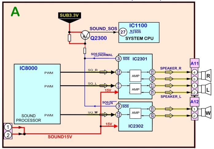
The transistor Q2300 monitors the speaker amplifiers ICs (IC2301 and IC2302). Pin 3 of both ICs is normally high. If any of these ICs or one of the speakers develops a short circuit, pin 3 goes low causing Q2300 to go into conduction and output a low to the base of Q2300. As a result, Q2300 comes on and outputs a high to pin 27 of the System CPU (IC1100) on the A board.
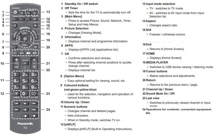
Remote Control
Troubleshooting
Before requesting service or assistance, please follow these simple guides to resolve the problem. If an error message appears, follow the message’s instructions. If the problem still persists, please contact your local Panasonic dealer for assistance
| Problem | Solution |
|---|---|
| Red, blue, green or black spots on the screen. | This is the characteristic of liquid crystal panels. The liquid crystal panel is built with very high precision technology. Occasionally, a few non-active pixels may appear on the screen as points of red, green, blue or black. This does not affect the performance of your TV and it is not a quality problem. |
| Chaotic image, noisy. | Set [P-NR] in the [Picture] menu to remove noise. Check nearby electrical products (car, motorcycle, fluorescent lamp). |
| No image is displayed. | Check the settings of [Contrast], [Brightness] or [Colour] in the [Picture] menu. Check the TV is in AV mode. If the TV is in AV mode, check the selected input mode match the output of the external equipment. |
| Blurry or distorted image. | (No sound or low volume.) Reset channels. |
| Unusual image is displayed. | Turn the TV off with Mains power On / Off switch, then turn it on again. If the problem persists, initialise all settings. |
| Pictures from equipment connected via HDMI are unusual. | Check the HDMI cable is connected properly. Turn the TV and equipment off, then turn them on again. Check an input signal from the equipment. Use equipment compliant with EIA/CEA-861/861D. |
| No sound is produced. | Check the sound mute setting and volume. |
| Low level or distorted sound. | Sound signal reception may be deteriorated. |
| Sound output via HDMI connection is unusual. | Set the sound setting of the connected equipment to “2ch L.PCM”. Check the [HDMI 1/2 Input(HDMI)] setting in the [Sound] menu. If digital sound connection has a problem, select analogue sound connection. |
| The TV goes into Standby mode. | This TV is equipped with auto power standby function. |
| The remote control does not work or is intermittent. | Replace the batteries. Point the remote control directly at the remote control signal receiver of the TV (within about 7 m and 30 degree angle). Situate the TV away from sunshine or block sources of bright light from shining on the remote control signal receiver of the TV. |
| Parts of the TV become hot. | Even if the temperature of parts of the front, top and rear panels has risen, these temperature rises do not cause any problems in terms of performance or quality. |
| Clattered sound might be heard. | There is some flexibility around the panel to prevent damage. This is not a malfunction. |
| Overcurrent error message appears. | he connected USB device might cause this error. Remove the device and turn the TV off with Mains power On / Off switch, then turn it on again. Check foreign objects are not inside the USB port. |

Care and Cleaning
First, unplug the Power cord plug from the wall outlet.
Display panel: The front of the display panel has been specially treated. Wipe the panel surface gently using only a cleaning cloth or a soft, lintfree cloth.
- If the surface is particularly dirty, after cleaning up the dust, soak a soft, lint-free cloth in diluted, mild liquid dish soap (1 part mild liquid dish soap diluted by 100 times the amount of water), and then wring the cloth to remove excess liquid. Use this cloth to wipe the surface of the display panel, then wipe it evenly with a dry cloth of the same type until the surface is dry.
- Do not scratch or hit the surface of the panel with fingernails or other hard objects. Furthermore, avoid contact with volatile substances such as insect sprays, solvents, and thinner; otherwise, the quality of the surface may be adversely affected.
Cabinet: If the cabinet becomes dirty, wipe it with a soft, dry cloth.
- If the cabinet is particularly dirty, soak the cloth in diluted, mild liquid dish soap and then wring the cloth dry. Use this cloth to wipe the cabinet and then wipe it dry with a dry cloth.
- Do not allow any mild liquid dish soap to come into direct contact with the surface of the Plasma TV. If water droplets get inside the unit, operating problems may result.
- Avoid contact with volatile substances such as insect sprays, solvents, and thinner; otherwise, the quality of the cabinet surface may be adversely affected or the coating may peel off.
- Do not let articles made from rubber or PVC be in contact with the TV for long periods of time.
Pedestal:
- Cleaning. Wipe the surfaces with a soft, dry cloth. If the unit is particularly dirty, clean it using a cloth soaked with water to which a small amount of mild liquid dish soap has been added and then wipe with a dry cloth. Do not use products such as solvents, thinner, or household wax for cleaning, as they can damage the surface coating. (If using a chemically-treated cloth, follow the instructions supplied with the cloth.)
- Do not attach sticky tape or labels, as they can make the surface of the pedestal dirty. Do not allow long-term contact with rubber, vinyl products, or the like. (Doing so will cause deterioration.)
Power cord plug: Wipe the plug with a dry cloth at regular intervals. (Moisture and dust can lead to fire or electrical shock.)