Vaillant combi boiler error codes are crucial for users. These codes provide essential information to understand the device’s performance and troubleshoot issues effectively. Identifying the correct code in case of a malfunction is key to initiating an efficient repair process.
Logical Fault Finding Procedure
These checks must be carried out before attempting to use the fault finding guide.
- Carry out electrical safety checks.
- Check that the external electricity supply to the boiler is on, and a supply of 230 V~ is present between boiler terminals ‘L’ and ‘N’.
- Check that the gas supply to the boiler is on, that it has been correctly purged and that an inlet pressure of 20 mbar is available at the gas valve. (See section ‘Gas Supply’).
- Ensure the heating system is full of water and charged to between 1 and 1.5 bar. If not, refill and vent the system. (See section ‘Filling the heating system’). Ensure boiler flow and return service valves are open.
- Check that the main on/off control is set to the ‘on’ position.
- Set the central heating temperature to maximum.
- Set the domestic hot water temperature to maximum (combination boilers only).
- Check that all external controls are on and calling for heat (if no external controls are fitted, boiler terminals 3 and 4 must be linked). Check that the boiler anti-cycling economiser is not engaged.
Status Codes
The status codes that you can see on the display provides information about the current operating condition of the appliance. The display of the status codes can be called as follows:
Press the “i” key. The display shows the status code, e.g. S.04 for “Burner mode – Heating”.
The display of the status codes can be cancelled as follows:
- Press the “i” key or
- Do not press any key for about 4 minutes. The current heating flow temperature appears in the display again.
| Display | Meaning |
|---|---|
| All models (heating mode) | |
| S.00 | No heat demand |
| S.01 | Fan running |
| S.02 | Water pump running |
| S.03 | Ignition sequence |
| S.04 | Burner ignited |
| S.05 | Fan and pump running |
| S.06 | Fan over run |
| S.07 | Pump over run |
| S.08 | Anti cycling mode |
| ecoTEC combination boilers only (Domestic hot water mode) | |
| S.10 | Hot water demand |
| S.11 | Fan running |
| S.13 | Ignition sequence |
| S.14 | Burner ignited |
| S.15 | Fan and pump running |
| S.16 | Fan over run |
| S.17 | Pump over run |
| ecoTEC combination boilers only (warm start) | |
| S.20 | Warmstart demand |
| S.21 | Fan running |
| S.22 | Pump running |
| S.23 | Ignition sequence |
| S.24 | Burner ignited |
| S.25 | Fan and water pump running |
| S.26 | Fan over run |
| S.27 | Pump over run |
| S.28 | Anti cycling mode |
| All Boilers | |
| S.30 | No heating demand from external controls |
| S.31 | Central heating thermostat knob turned off or no heat demand by the eBUS control unit |
| S.32 | Heat exchanger antifreeze active, as fan speed variation is too high. Appliance is within the waiting time of the operation block function |
| S.34 | Antifrost mode active |
| S.36 | No heating demand from low voltage controls |
| S.42 | Response from accessory modul or defective condensate pump is blocking burner operation |
| S.53 | Appliance is within the waiting period of the operation block function due to water shortage |
| S.54 | Appliance is within the waiting period of the operation block function due to water shortage |
| S.76 | Appliance is within the waiting period of the operation block function due to water shortage |
| S.96 | Return-sensor check is running, demand |
| S.97 | Waterpressure sensor check is running, demand |
| S.98 | Flow-/Return-sensor check is running, demand |
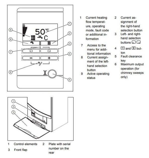
Operator Control Panel
Diagnostic Codes
In the diagnostic mode, you can change certain parameters or display more information. The diagnostic information is divided into two diagnostic levels. The second diagnostic level can be reached only after entering level.
First Diagnostic level
- Press the “i” and “+” keys simultaneously. The display shows “d.00”.
- Use the “+” or “–” keys to scroll through the desired diagnostic numbers of the first diagnostic level
- Press the “i” key. The display shows the relevant diagnostic information.
- If necessary, use the “+” or “–” keys to change the value
- Save the new value by holding down the “i” key for approx. 5 seconds until the display no longer flashes.
You can end the diagnostic mode as follows:
- Press the “i” and “+” keys simultaneously.
- Do not press any key for approx. 4 minutes.
The current heating flow temperature appears in the display again.
Second diagnostic level
- As described above in the first diagnostic level, scroll through the diagnostic number d.97.
- Change the displayed value to 17 (password) and press the “i” button.
You are now in the second diagnostic level where all information from the first diagnostic level and the second diagnostic level is displayed. Scrolling and changing values and exiting the diagnostic mode is done as described in the first diagnostic level.
Note: After exiting the second diagnostic level, if you press “i” and “+” within 4 minutes, you will directly reach the second diagnostic level without having to enter the password again.
| Display | Meaning |
|---|---|
| d.00 | Heating part load |
| d.01 | Water pump over run time for heating mode |
| d.02 | Max. burner anti cycling period at 20 °C Flow temperature |
| d.03 | Hot water flow temperature reading (combination boiler only) |
| d.04 | Current temperature for warm start sensor |
| d.05 | Flow temperature target value or return target value when return regulation is set. |
| d.06 | Hot water temperature target value |
| d.07 | Warm start temperature target value. Storage temperature target value |
| d.08 | External controls heat demand |
| d.09 | Flow target temperature from external analogue regulator to terminal 7-8-9/eBUS |
| d.10 | Status internal heating pump |
| d.11 | Status external heating pump |
| d.13 | Hot water circulation pump |
| d.22 | Hot water demand |
| d.23 | Summer/Winter function |
| d.25 | Hot water activation via eBUS Control |
| d.40 | Flow temperature |
| d.41 | Return temperature |
| d.47 | Outside temperature |
| d.67 | Remaining burner anti cycling time |
| d.76 | Appliance variant |
| d.90 | Digital regulator status |
| d.91 | DCF status with connected external probe with DCF77 receiver |
| d.97 | Activation of the second diagnostic level |
| d.17 | Heating flow/return regulation changeover |
| d.18 | Pump mode |
| d.19 | Only in ecoTEC plus: Operating modes of the two-stage heating pump |
| d.27 | Switching accessory relay 1 in the accessory module |
| d.28 | Switching accessory relay 2 in the accessory module |
| d.30 | Control signal for both gas valves |
| d.33 | Fan speed target value |
| d.34 | Fan speed actual value |
| d.35 | Position of diverter valve |
| d.36 | Hot water flow sensor |
| d.44 | Ionisation current |
| d.50 | Offset for minimum speed |
| d.51 | Offset for maximum speed |
| d.60 | Number of safety temperature limiter cut offs |
| d.61 | Number of lock outs |
| d.64 | Average ignition time |
| d.65 | Maximum ignition time |
| d.68 | Unsuccessful ignitions in the first attempt |
| d.69 | Unsuccessful ignitions in the second attempt |
| d.70 | Set diverter valve position |
| d.71 | Maximum setting of heater control knob |
| d.72 | Pump overrun time after charging an electronically controlled hot water storage |
| d.73 | Offset for warm start target value |
| d.75 | Maximum charging time for a storage without own controller |
| d.77 | Storage partial load |
| d.78 | Storage charging temperature limit |
| d.80 | Heating operating hours |
| d.81 | Water heating operating hours |
| d.82 | Cycles in heating mode |
| d.83 | Cycles in hot water operation |
| d.84 | Maintenance indicator: Number of hours until the next maintenance |
| d.93 | DSN appliance variant setting |
| d.96 | Factory setting |
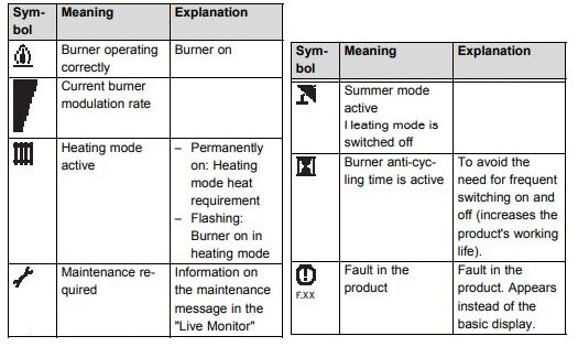
Displayed Symbols
Fault Codes
Fault codes take priority over all other display functions in the event of a system fault occurring. If multiple faults occur, the corresponding fault codes are displayed alternately for about two seconds each.
The fault memory stores details of the ten most recent faults.
- Press the ”i” and ”–” buttons simultaneously.
- Use the ”+” button to scroll back through the list of memorised errors.
To cancel fault error memory display mode, proceed as follows:
- Press the ”i” button below the display or
- Do not touch any key for about four minutes. The display will now revert back to showing the current flow temperature.
| Code | Cause |
|---|---|
| F.00 | NTC broken, NTC cable broken, Defective connection at NTC, Defective connection at electronics |
| F.01 | NTC broken, NTC cable broken, Defective connection at NTC, Defective connection at electronics |
| F.02 | NTC-connector not plugged in or loose, NTC defective connector on the electronics not plugged in correctly, cable defective |
| F.10 | NTC defective,cable/casing shortcut |
| F.11 | NTC defective, cable/casing shortcut |
| F.13 | NTC defective,short circuit in cable harness, cable/casing shortcut |
| F.20 | Flow-NTC not correctly thermal-connected or defective; appliance does not shut down |
| F.22 | Too little water in the appliance, water pressure sensor defective, cable to pump or water sensor defective, pump blocked or defective, pump output too low |
| F.23 | Pump blocked or defective, pump output too low, flow and return NTC interchanged |
| F.24 | Pump blocked, insufficient pump output, air in appliance, water pressure too low |
| F.27 | Flame detector defective |
| F.28 | Faults in the gas supply such as: - Gas meter or gas pressure detector defective - Air in gas - Gas flow pressure too low - Fire protection tap has disengaged Faults in the gas valve, wrong gas setting, igniter (ignition transformer, ignition cable, ignition plug) defective, ionisation current stopped (cable, electrode), faulty earthing in appliance, electronics defective |
| F.29 | Gas supply temporarily stopped, faulty earthing of appliance |
| F.32 | Fan blocked, plug not inserted correctly on fan, hall sensor defective, fault in cable harness, electronics defective |
| F.49 | Short circuit on eBUS, overload on eBUS or two power sources on eBUS with different polarity |
| F.61 | Short circuit/earth (ground) leak in cable harness to gas valves, gas valve assembly defective (earth/ground leak from coils), electronic control system defective |
| F.62 | Gas valve leaking, electronics defective |
| F.63 | Electronics defective |
| F.64 | Short-circuit in flow or return NTC or electronics defective |
| F.65 | Electronics too hot due to external effect, electronics defective |
| F.70 | Spare part failure display and maiboard interchanged at same time and device specific number not adjusted |
| F.71 | Flow NTC is defective |
| F.72 | Flow and/or return NTC is defective (tolerances too big) |
| F.73 | Cable to water pressure sensor is broken or has a short-circuit at 0 V or water pressure sensor defective |
| F.74 | Cable to water pressure sensor has a short-circuit at 5 V / 24 V or internal fault in water pressure sensor |
| F.75 | Water pressure sensor or/and pump defective Too little water in appliance; check adjustable by-pass; connect external expension vessel to return |
| F.76 | Cable or cable connection of fuse in the primary heat exchanger defective, or primary heat exchanger defective |
| F.77 | condensate pump defective or flume flap feedback triggered |
| F.78 | link box VR65 connected to combination boiler |
| con | connection error display mainboard |
Test Programs
Special functions can be triggered on the appliances by activating various test programs. These programs are given in detail in the table.
- The test programs P.0 to P.6 will be started when “Power ON” is turned on and the “+” key is pressed for 5 s. The display shows “P.0”.
- Press the “+” key to start counting the test number upwards.
- Press the “i” to operate the appliance now and to start the test program.
- Press “i” and “+” simultaneously to exit the test programs. You can also exit the test programs by not pressing any key for 15 minutes.
| Display | Meaning |
|---|---|
| P.0 | Bleeding test program. The heating circuit and hot water circuit (combination boiler only) is bled via the automatic air vent (the cap on the automatic air vent must be loosened). |
| P.1 | Test program where the appliance is operated in full load after successful ignition |
| P.2 | Test program where the appliance is operated with minimum gas volume (ignition gas volume) after successful ignition |
| P.3 | not available |
| P.4 | not available |
| P.5 | Test program for the safety temperature limit check; appliance heats up by by-passing a regulating shutdown through the flow regulator until the shutoff temperature of 97 °C is achieved. |
| P.6 | Filling test program. The diverter valve moves to the centre position |